VFD Torque Calculation Accuracy
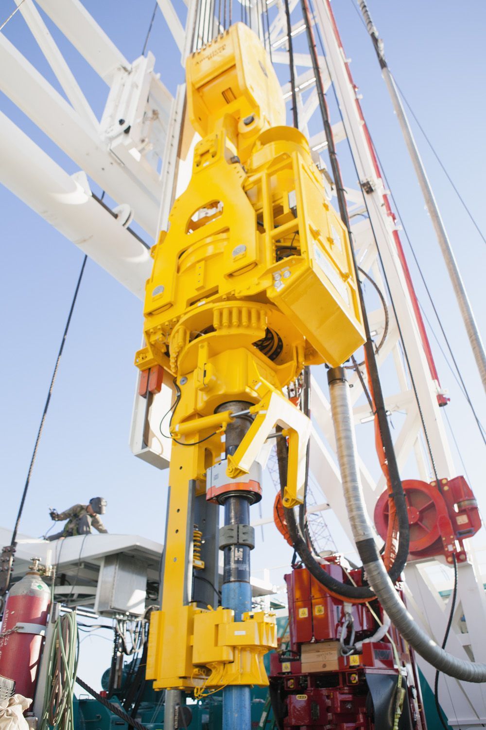
Everything showed “torque limit reached.” The drill pipe said otherwise…
During top drive commissioning, the driller set 12,000 Nm. Both motors were contributing. Nothing was “fighting.” But the measured torque on the drill pipe? Barely ~10,500–11,000 Nm.
Everything on the drive said we were at limit. Reality said otherwise.
Here’s what was actually happening:
At ~20 RPM (vs 800 RPM rated), back EMF is almost negligible.
So the drive can’t rely on voltage feedback. It leans heavily on the motor model.
T∝ϕ⋅Iq
Flux (φ) comes from magnetizing inductance (Lm).
But that’s just one piece.
The drive’s torque estimation depends on a full motor model: • Magnetizing inductance (Lm) → defines flux • Rotor resistance (Rr) → affects slip & torque production • Stator resistance (Rs) → critical at low speed • Leakage inductance → impacts current dynamics
If these are off → torque estimation drifts.
The drive “thinks” it hit 12,000 Nm. Physically, it hasn’t.
Now here’s where it gets dangerous.
This isn’t just a number mismatch.
• Connections get under-torqued → joints can loosen downhole • Driller compensates → pushes higher torque → hidden overload risk • One motor can run closer to thermal limits • Gearbox sees uneven stress over time
All while the system says: “Everything is fine.”
We had already done motor ID runs. Still wrong.
So we manually tuned magnetizing inductance in both drives. Only then did the commanded torque limit match measured torque.
Why This Problem is WORSE at Low Speed
At low speed: Back EMF is low Voltage model accuracy drops Estimation depends heavily on parameters
So: Parameter mismatch impact ∝ 1 / speed
Lesson learned: At low speed, torque accuracy is not a control problem. It’s a model accuracy problem.
Have you ever trusted a torque value… and later realized it wasn’t real?